- 您现在的位置:买卖IC网 > Sheet目录318 > CAT9532WI-T1 (ON Semiconductor)IC LED DRIVER LINEAR 24-SOIC
�� �
�
�CAT9532�
�Acknowledge�
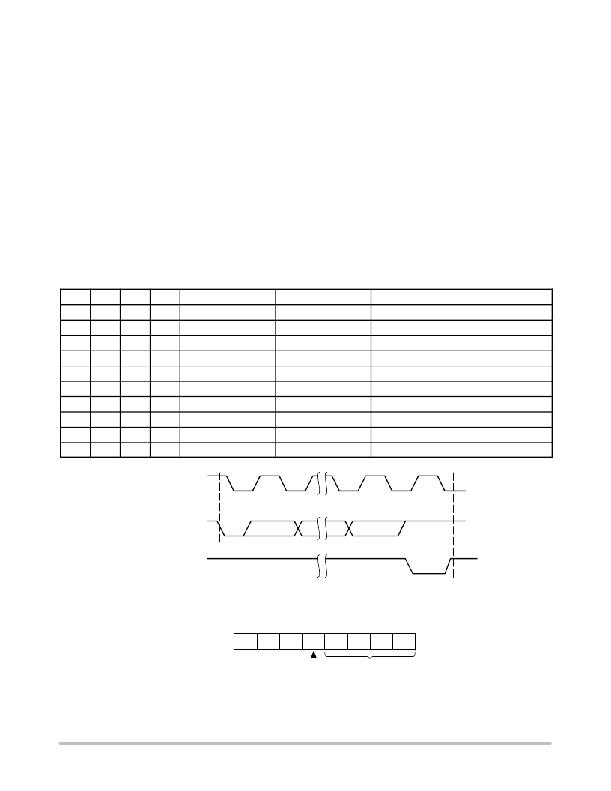
�After� a� successful� data� transfer,� each� receiving� device� is�
�required� to� generate� an� acknowledge.� The� acknowledging�
�device� pulls� down� the� SDA� line� during� the� ninth� clock� cycle,�
�signaling� that� it� received� the� 8� bits� of� data.� The� SDA� line�
�remains� stable� LOW� during� the� HIGH� period� of� the�
�acknowledge� related� clock� pulse� (Figure� 7).�
�The� CAT9532� responds� with� an� acknowledge� after�
�receiving� a� START� condition� and� its� slave� address.� If� the�
�device� has� been� selected� along� with� a� write� operation,� it�
�responds� with� an� acknowledge� after� receiving� each� 8� ?� bit�
�byte.�
�When� the� CAT9532� begins� a� READ� mode� it� transmits� 8�
�bits� of� data,� releases� the� SDA� line,� and� monitors� the� line� for�
�an� acknowledge.� Once� it� receives� this� acknowledge,� the�
�CAT9532� will� continue� to� transmit� data.� If� no� acknowledge�
�is� sent� by� the� Master,� the� device� terminates� data� transmission�
�and� waits� for� a� STOP� condition.� The� master� must� then� issue�
�Table� 6.� INTERNAL� REGISTERS� SELECTION�
�a� stop� condition� to� return� the� CAT9532� to� the� standby� power�
�mode� and� place� the� device� in� a� known� state.�
�Registers� and� Bus� Transactions�
�After� the� successful� acknowledgement� of� the� slave�
�address,� the� bus� master� will� send� a� command� byte� to� the�
�CAT9532� which� will� be� stored� in� the� Control� Register.� The�
�format� of� the� Control� Register� is� shown� in� Figure� 8.�
�The� Control� Register� acts� as� a� pointer� to� determine� which�
�register� will� be� written� or� read.� The� four� least� significant�
�bits,� B0,� B1,� B2,� B3,� are� used� to� select� which� internal�
�register� is� accessed,� according� to� the� Table� 6.�
�If� the� auto� increment� flag� (AI)� is� set,� the� four� least�
�significant� bits� of� the� Control� Register� are� automatically�
�incremented� after� a� read� or� write� operation.� This� allows� the�
�user� to� access� the� CAT9532� internal� registers� sequentially.�
�The� content� of� these� bits� will� rollover� to� “0000”� after� the� last�
�register� is� accessed.�
�B3�
�0�
�0�
�0�
�0�
�0�
�0�
�0�
�0�
�1�
�1�
�B2�
�0�
�0�
�0�
�0�
�1�
�1�
�1�
�1�
�0�
�0�
�B1�
�0�
�0�
�1�
�1�
�0�
�0�
�1�
�1�
�0�
�0�
�B0�
�0�
�1�
�0�
�1�
�0�
�1�
�0�
�1�
�0�
�1�
�Register� Name�
�INPUT0�
�INPUT1�
�PSC0�
�PWM0�
�PSC1�
�PWM1�
�LS0�
�LS1�
�LS2�
�LS3�
�Type�
�READ�
�READ�
�READ/WRITE�
�READ/WRITE�
�READ/WRITE�
�READ/WRITE�
�READ/WRITE�
�READ/WRITE�
�READ/WRITE�
�READ/WRITE�
�Register� Function�
�Input� Register� 0�
�Input� Register� 1�
�Frequency� Prescaler� 0�
�PWM� Register� 0�
�Frequency� Prescaler� 1�
�PWM� Register� 1�
�LED� 0� ?� 3� Selector�
�LED� 4� ?� 7� Selector�
�LED� 8� ?� 11� Selector�
�LED� 12� ?� 15� Selector�
�SCL� FROM�
�MASTER�
�1�
�8�
�9�
�DATA� OUTPUT�
�FROM� TRANSMITTER�
�DATA� OUTPUT�
�FROM� RECEIVER�
�START�
�Figure� 7.� Acknowledge� Timing�
�ACKNOWLEDGE�
�0�
�0�
�0�
�AI�
�B3�
�B2�
�B1�
�B0�
�RESET� STATE:� 00h�
�REGISTER� ADDRESS�
�AUTO� ?� INCREMENT� FLAG�
�Figure� 8.� Control� Register�
�http://onsemi.com�
�7�
�发布紧急采购,3分钟左右您将得到回复。
相关PDF资料
CAT9552HV6I-TG2
IC LED DRIVER LINEAR 24-TQFN
CAV24C02YE-GT3
IC EEPROM I2C SRL 2KB 8TSSOP
CAV24C04YE-GT3
IC EEPROM 4KB I2C SER 8TSSOP
CAV24C08YE-GT3
IC EEPROM I2C SRL 8KB 8TSSOP
CAV24C16YE-GT3
IC EEPROM I2C SRL 16KB 8TSSOP
CAV24C32YE-GT3
IC EEPROM I2C SRL 32KB 8TSSOP
CAV24C64YE-GT3
IC EEPROM I2C SRL 64KB 8TSSOP
CAV4201TD-GT3
IC LED DVR 350MA STP-DN TSOT23-5
相关代理商/技术参数
CAT9532WI-T1
制造商:ON Semiconductor 功能描述:IC PROGRAMMABLE LED DIMMER SOIC-24
CAT9532WI-T1-CUT TAPE
制造商:ON 功能描述:CAT9532 Series 25 mA 5.5 V 400 kHz I2C 16-bit Programmable LED Dimmer - SOIC-24
CAT9532YI
功能描述:LED照明驱动器 16-Bit Prog LED Dimmer w/Interface RoHS:否 制造商:STMicroelectronics 输入电压:11.5 V to 23 V 工作频率: 最大电源电流:1.7 mA 输出电流: 最大工作温度: 安装风格:SMD/SMT 封装 / 箱体:SO-16N
CAT9532YI-T2
功能描述:LED照明驱动器 I2C/SMBus Expander w/LED Dimming RoHS:否 制造商:STMicroelectronics 输入电压:11.5 V to 23 V 工作频率: 最大电源电流:1.7 mA 输出电流: 最大工作温度: 安装风格:SMD/SMT 封装 / 箱体:SO-16N
CAT9534HV4I-G
制造商:Rochester Electronics LLC 功能描述: 制造商:Catalyst Semiconductor 功能描述:
CAT9534HV4I-GT2
功能描述:接口-I/O扩展器 8-BIT I2C/SMBUS I/O PORT RoHS:否 制造商:NXP Semiconductors 逻辑系列: 输入/输出端数量: 最大工作频率:100 kHz 工作电源电压:1.65 V to 5.5 V 工作温度范围:- 40 C to + 85 C 安装风格:SMD/SMT 封装 / 箱体:HVQFN-16 封装:Reel
CAT9534HV4I-GT2-CUT TAPE
制造商:ON 功能描述:CAT9534 Series 2.3 to 5.5 V 8-bit 8 I/O I? and SMBus I/O Port - TQFN-16
CAT9534WI-GT2
功能描述:接口-I/O扩展器 8B I2C &SMBus I/O PORT RoHS:否 制造商:NXP Semiconductors 逻辑系列: 输入/输出端数量: 最大工作频率:100 kHz 工作电源电压:1.65 V to 5.5 V 工作温度范围:- 40 C to + 85 C 安装风格:SMD/SMT 封装 / 箱体:HVQFN-16 封装:Reel